Smart Farm Assembly
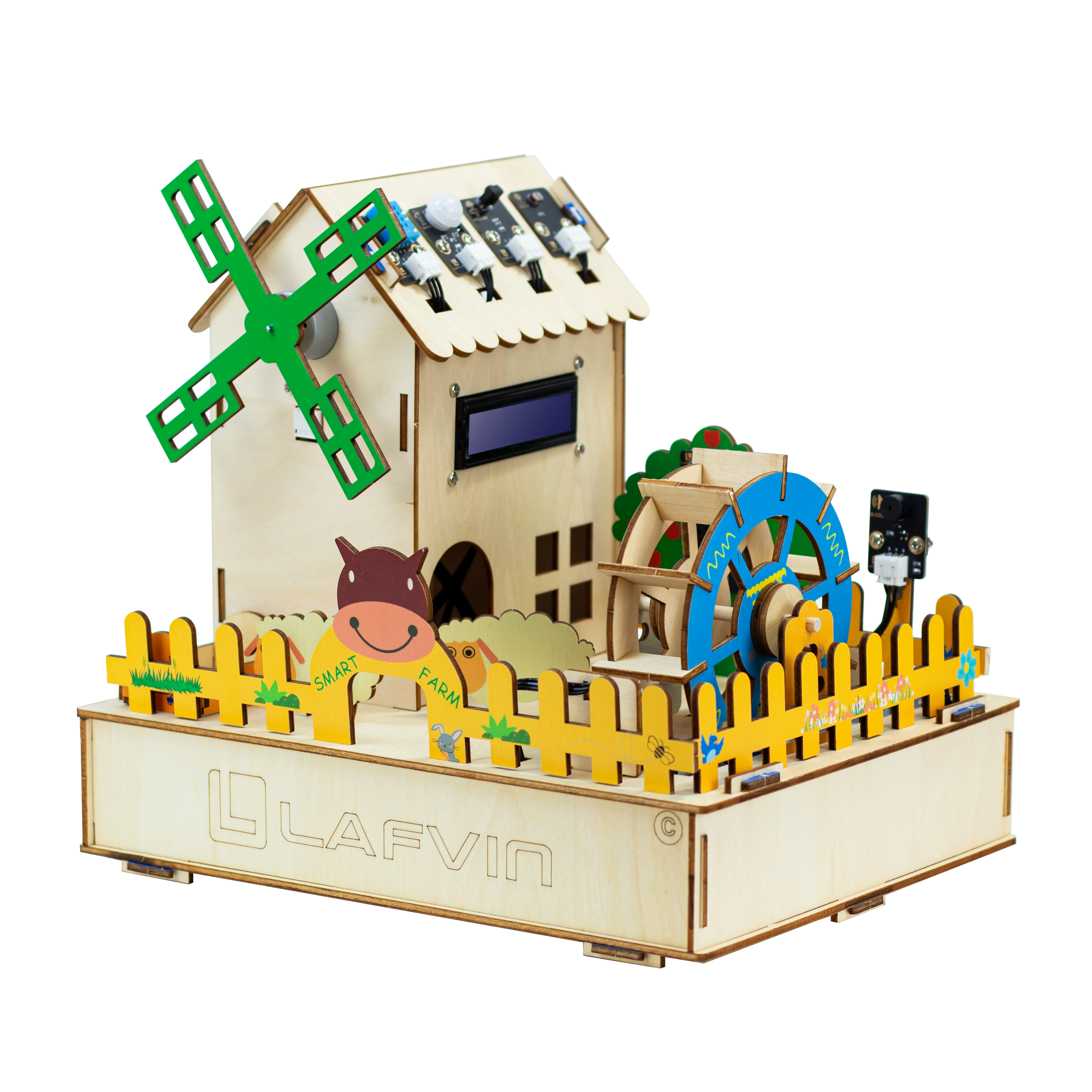
Assembly Video
The video contains an assembly tutorial for the smart farm. By watching this video, you can quickly assemble it.
If you need a more detailed assembly tutorial, please continue to view the text and image tutorial below.
Wiring Diagram
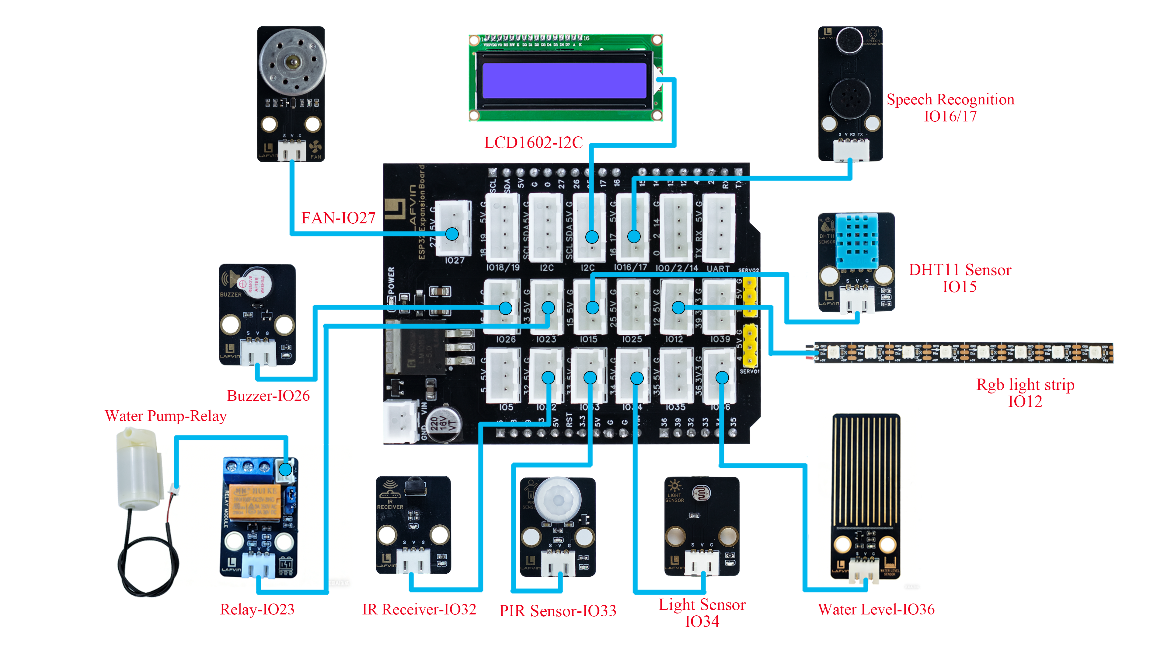
Component |
ESP32 Pin |
|---|---|
Relay Module |
23 |
Active Buzzer |
26 |
Fan |
27 |
PIR Sensor |
33 |
Light Sensor |
34 |
Infrared Receiver Module |
32 |
DHT11 Sensor |
15 |
Water Level Sensor |
36 |
Speech Recognition |
16, 17 |
LCD1602 |
I2C-SCL、SDA |
RGB Light Strip |
12 |
Warning
To ensure that each module works properly, please connect the wires as shown in the following image:
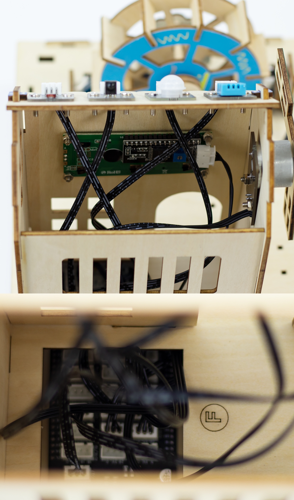
The four sensor modules (DHT11, PIR, IR Receiver, and Light)、motor fan module and LCD1602 screen on the roof pass through the interior of the house and are connected to the expansion board via holes marked “F” in the wooden planks.
 The sensor modules below are passed through the corresponding holes as shown in the diagram and connected to the expansion board.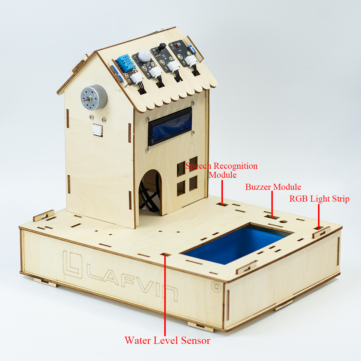
1. Base Assembly
Step 1: Install ESP32
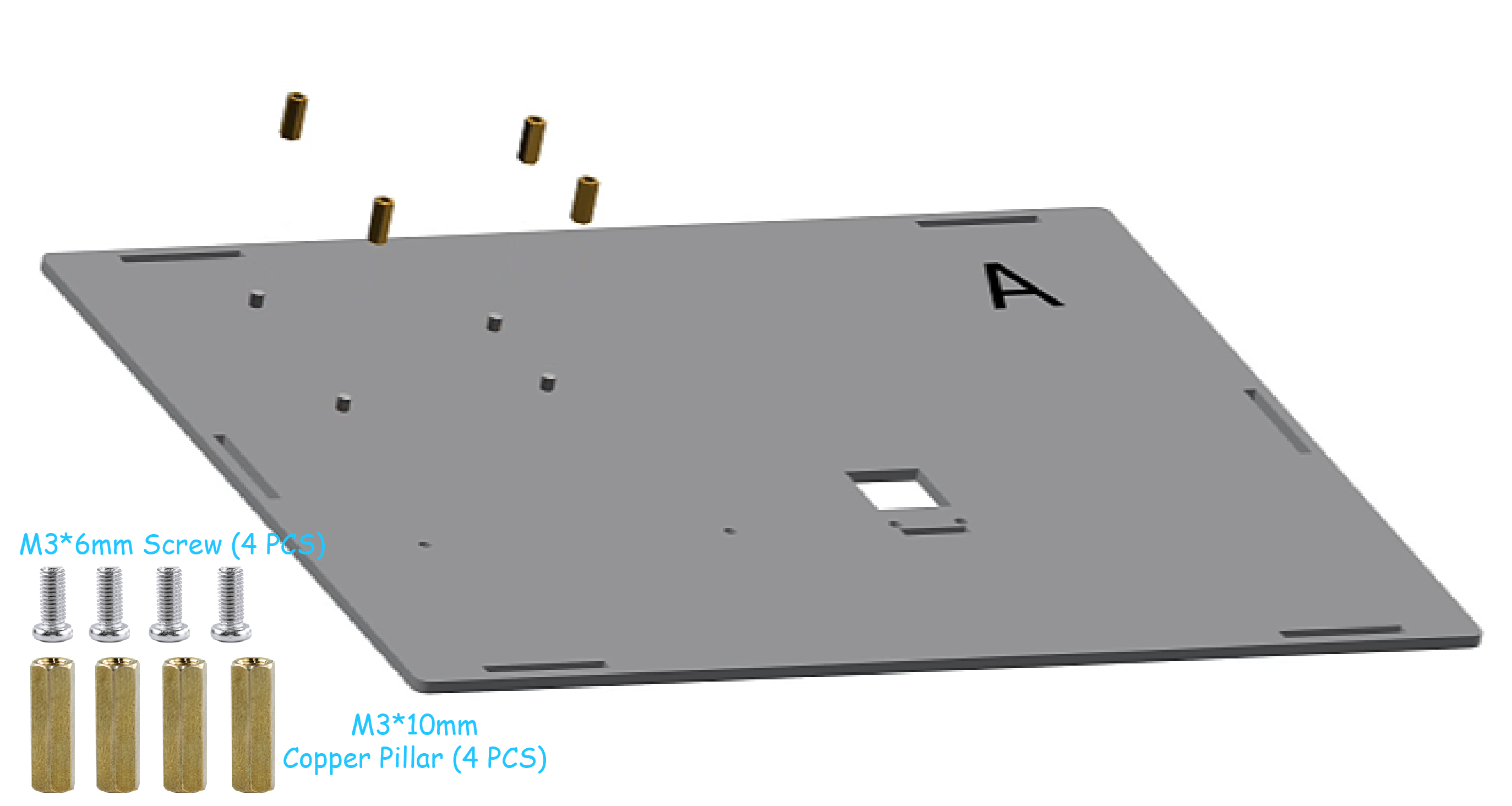
Step 1-1: Mounting screws
Parts list: Basswood board with “A”、 M3*6mm screw (4 PCS)、 M3*10mm copper pillar(4 PCS).
Precautions
The serial numbers on the basswood boards are used only to distinguish one board from another. In the tutorial examples, the serial numbers face outward for ease of illustration, but they should face inward during installation. This principle should also be followed for subsequent basswood installations.
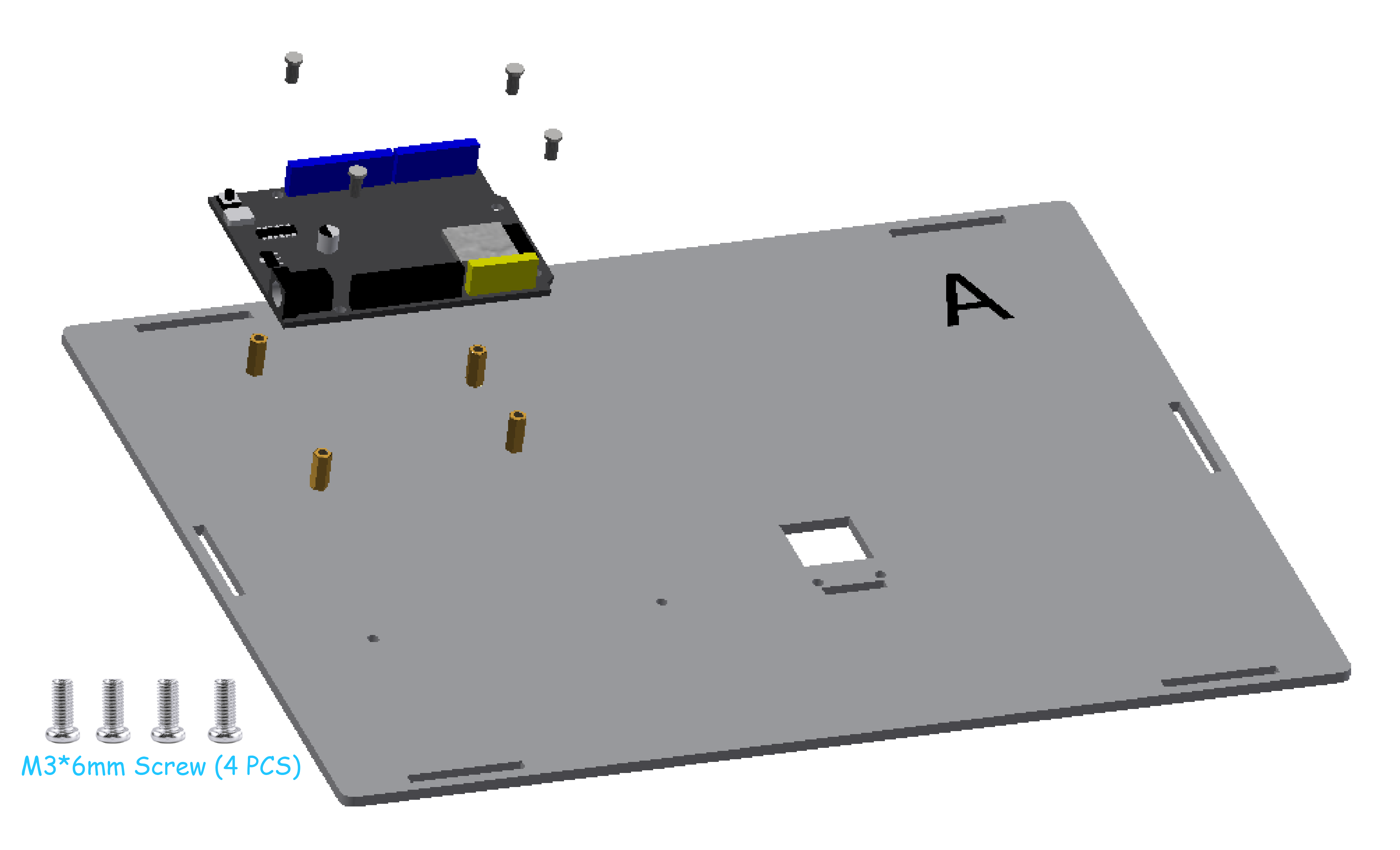
Step 1-2: Install ESP32
Parts list: ESP32 development board、M3*6mm screw (4 PCS).
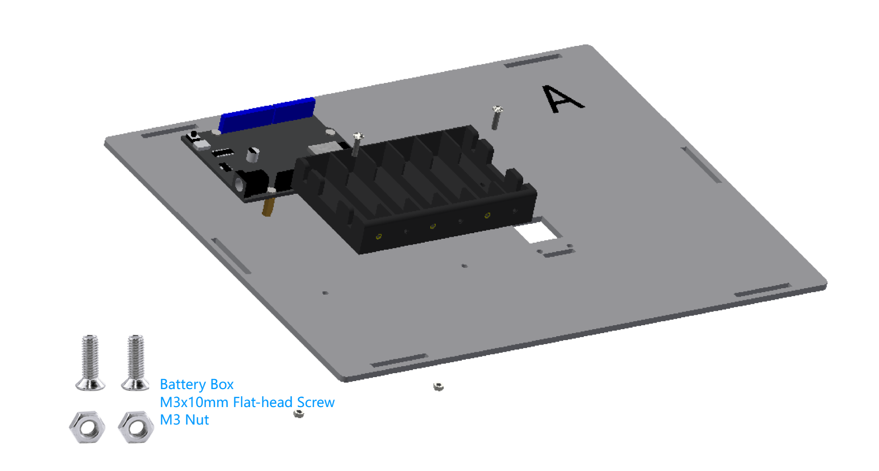
Step 2: Install Battery Box
Parts list: Battery Box 、M3*10mm Flat-head screw (2 PCS)、M3 Nut(2 PCS).
Precautions
When securing the battery compartment, use flat-head screws. If you use round-head screws, the screws will protrude and press against the battery, preventing it from being installed properly.
Batteries are not included in the package; you will need to bring your own 6 AA batteries.
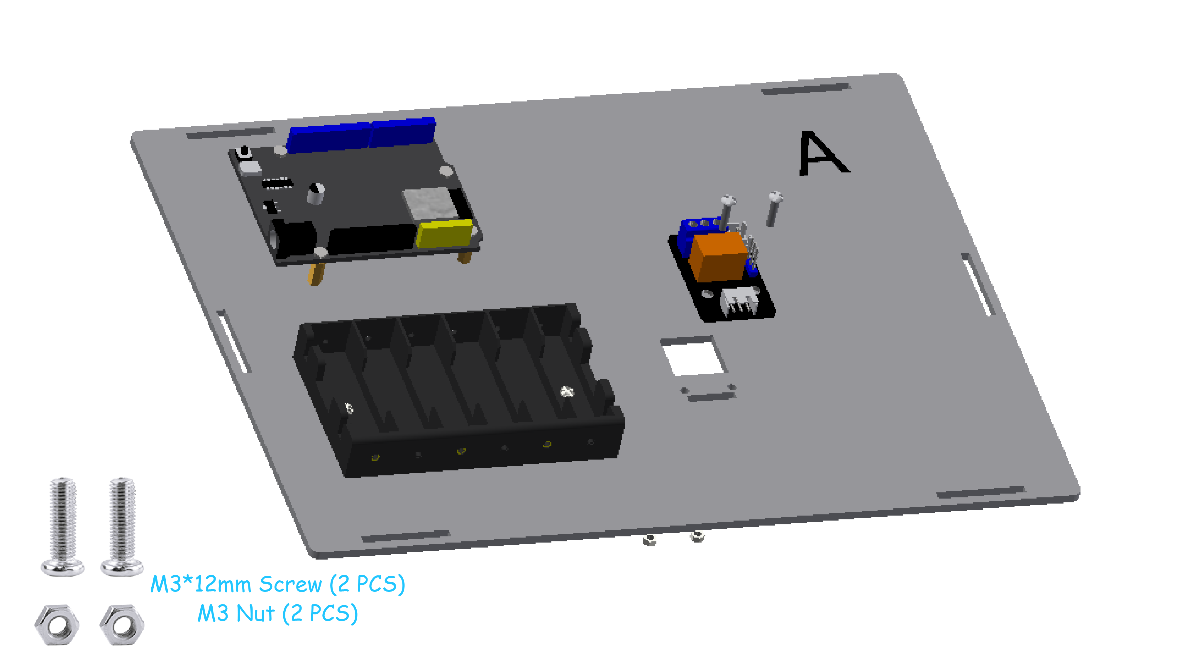
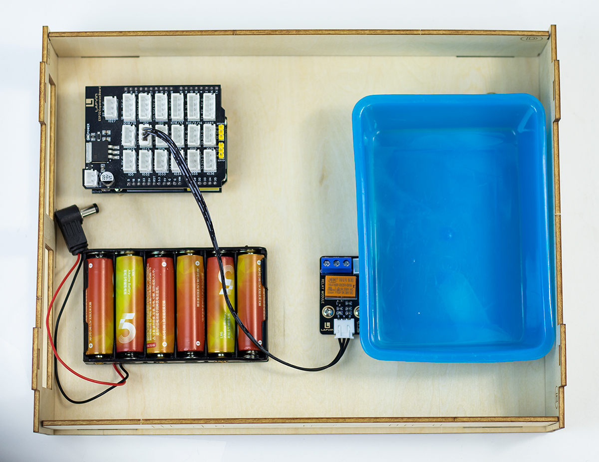
Step 3: Install Relay Module
Parts list: Relay Module 、M3*12mm screw (2 PCS)、M3 Nut(2 PCS).
Precautions
In this step, connect the expansion board to the ESP32 development board.
Then connect the relay module to pin IO23 of the expansion board using a 3-pin wire.
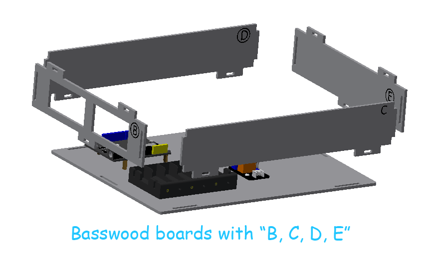
Step 4: Install Fence
Parts list: Basswood boards with “B, C, D, E”.
Step 5: Install Water Tank
Parts list: Water Tank、Glue(3 PCS).
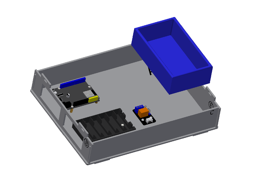
Precautions
Use three round adhesive dots to stick to the bottom of the sink, adjust their position, and fix them to the wooden board A.
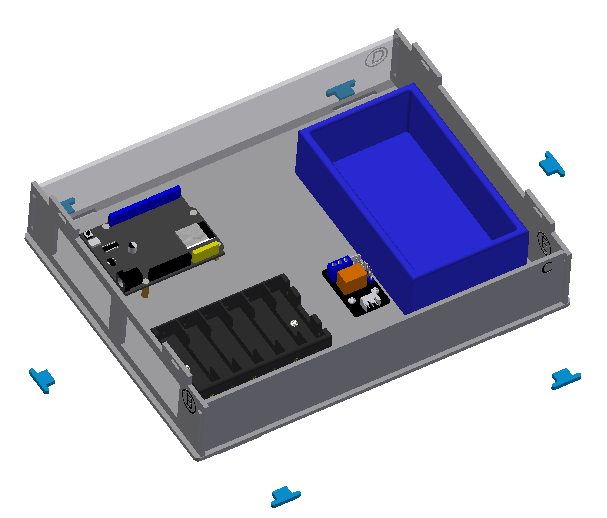
Step 6:Install Latch
Parts list: Blue Latch(6 PCS).
Step 7:Install Cover Plate
Parts list: Basswood boards with “F”.
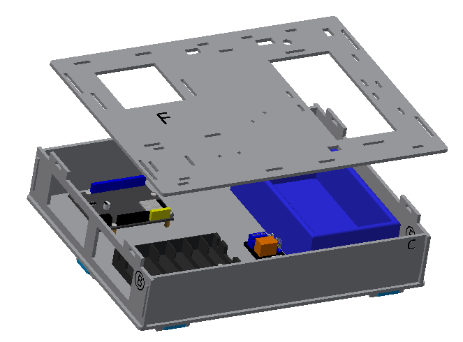
The assembled base is shown in the picture.
2. House Assembly
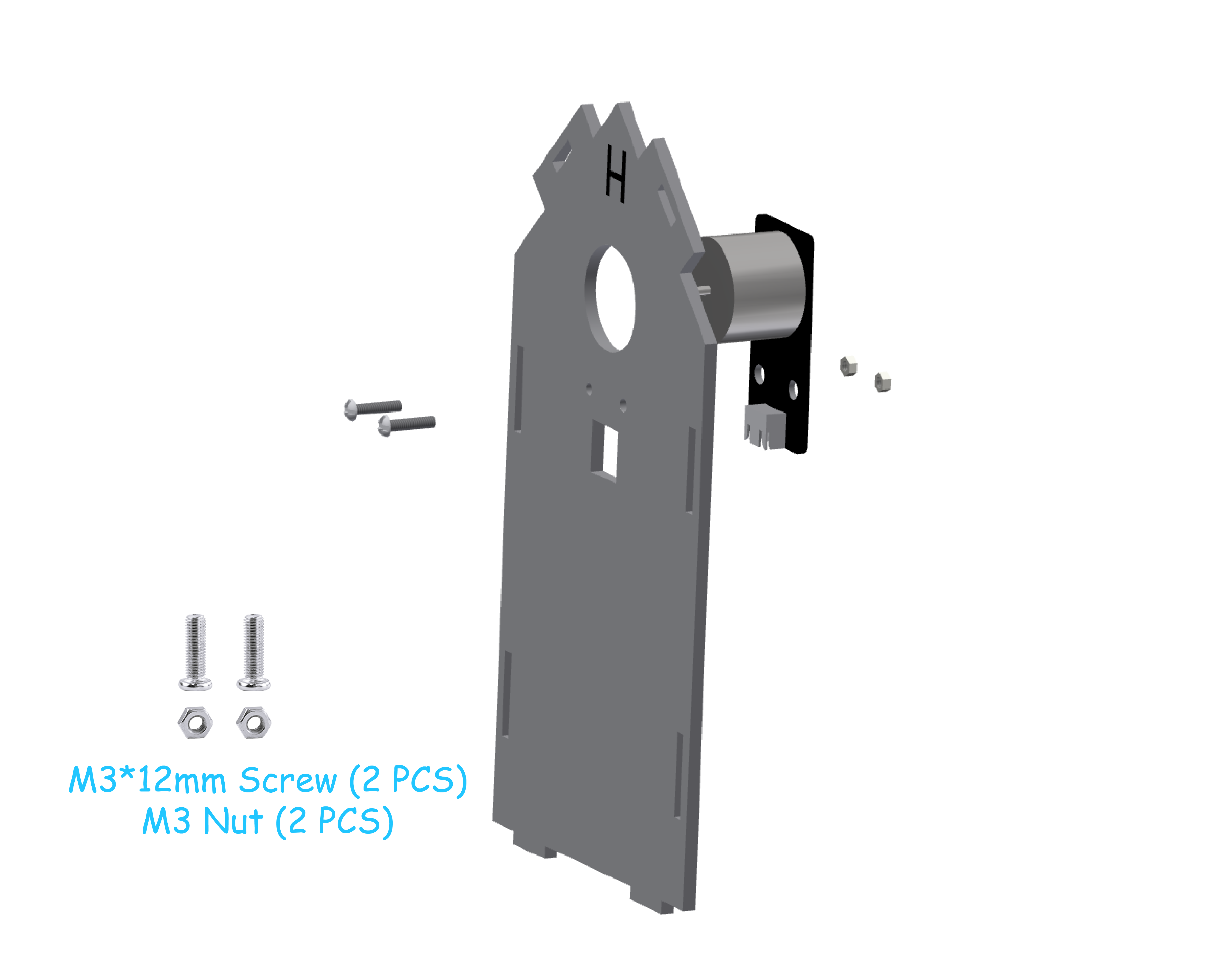
Step 1:Install Fan Module
Parts list: Basswood boards with “H”、Fan Module、M3*12mm screw (2 PCS)、M3 Nut(2 PCS).
Precautions
This step requires using a 3-pin wire to connect the fan module to pin IO27 of the expansion board.
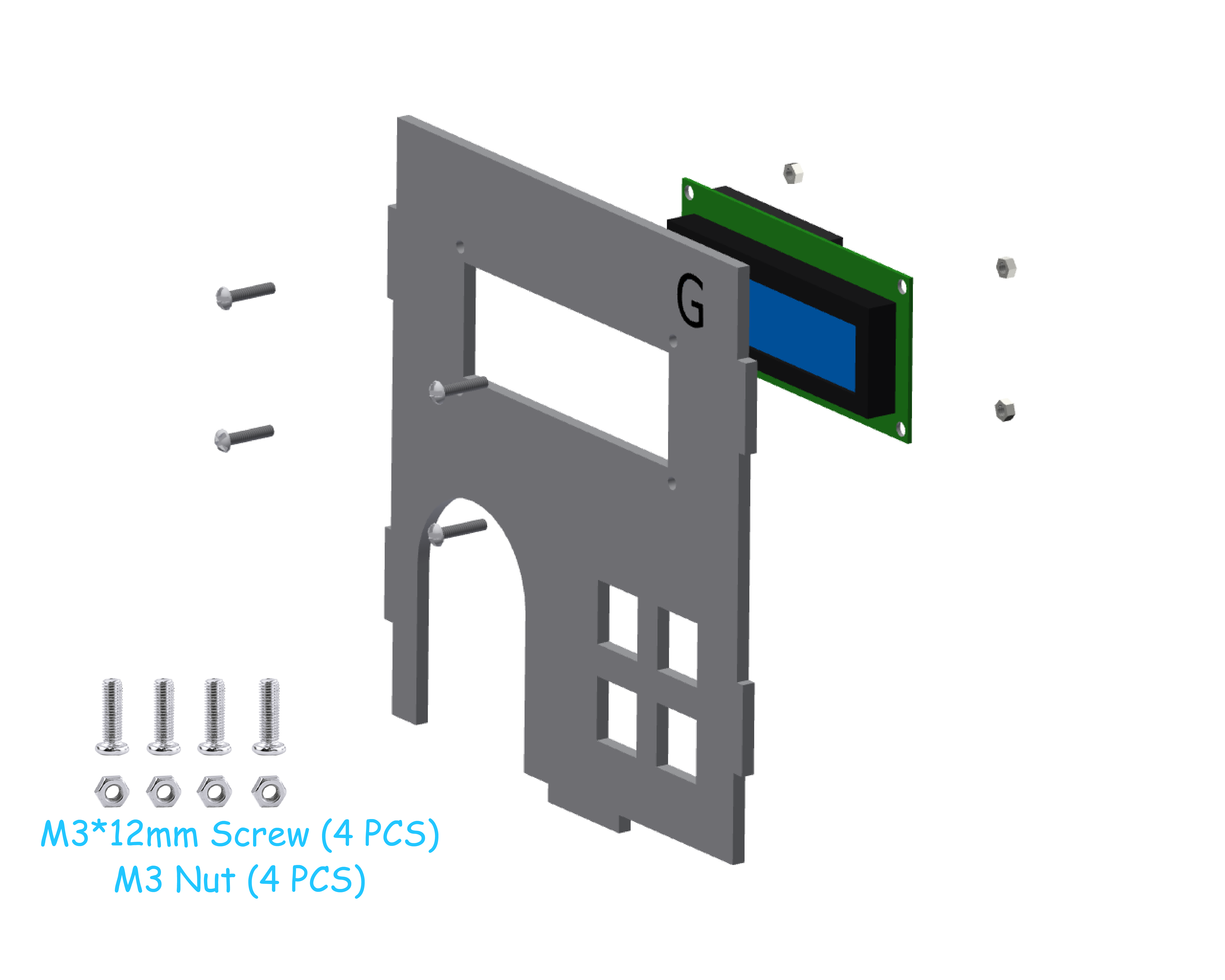
Step 2:Install LCD1602 Screen
Parts list: Basswood boards with “G”、LCD1602 Screen、M3*12mm screw (4 PCS)、M3 Nut(4 PCS).
Precautions
This step requires using a 4-pin wire to connect the LCD1602 screen to the I2C pin of the expansion board.
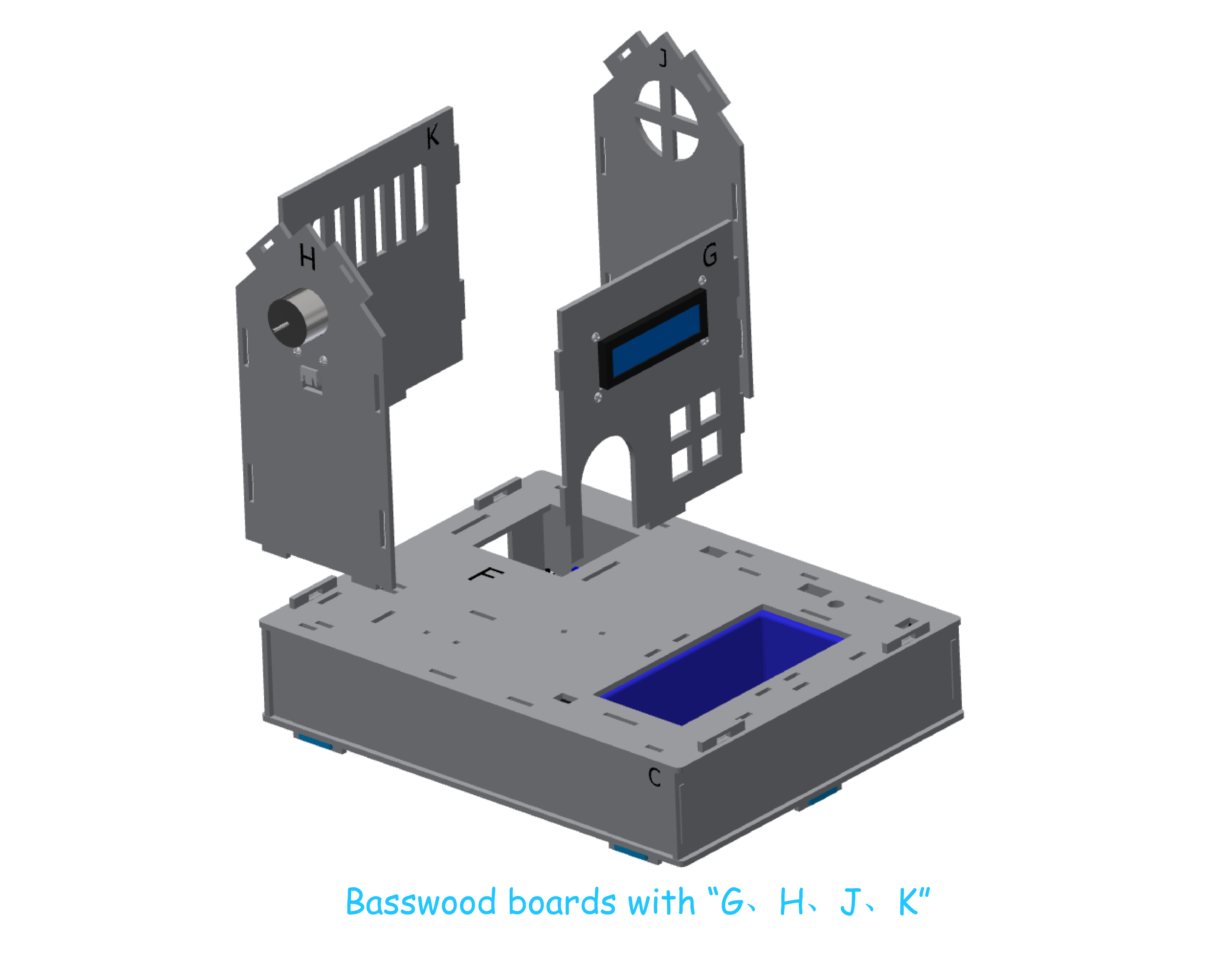
Step 3:Install House
Parts list: Basswood boards with “G、H、J、K”、
Step 4:Install Roof
Step 4-1:Install sensor Module
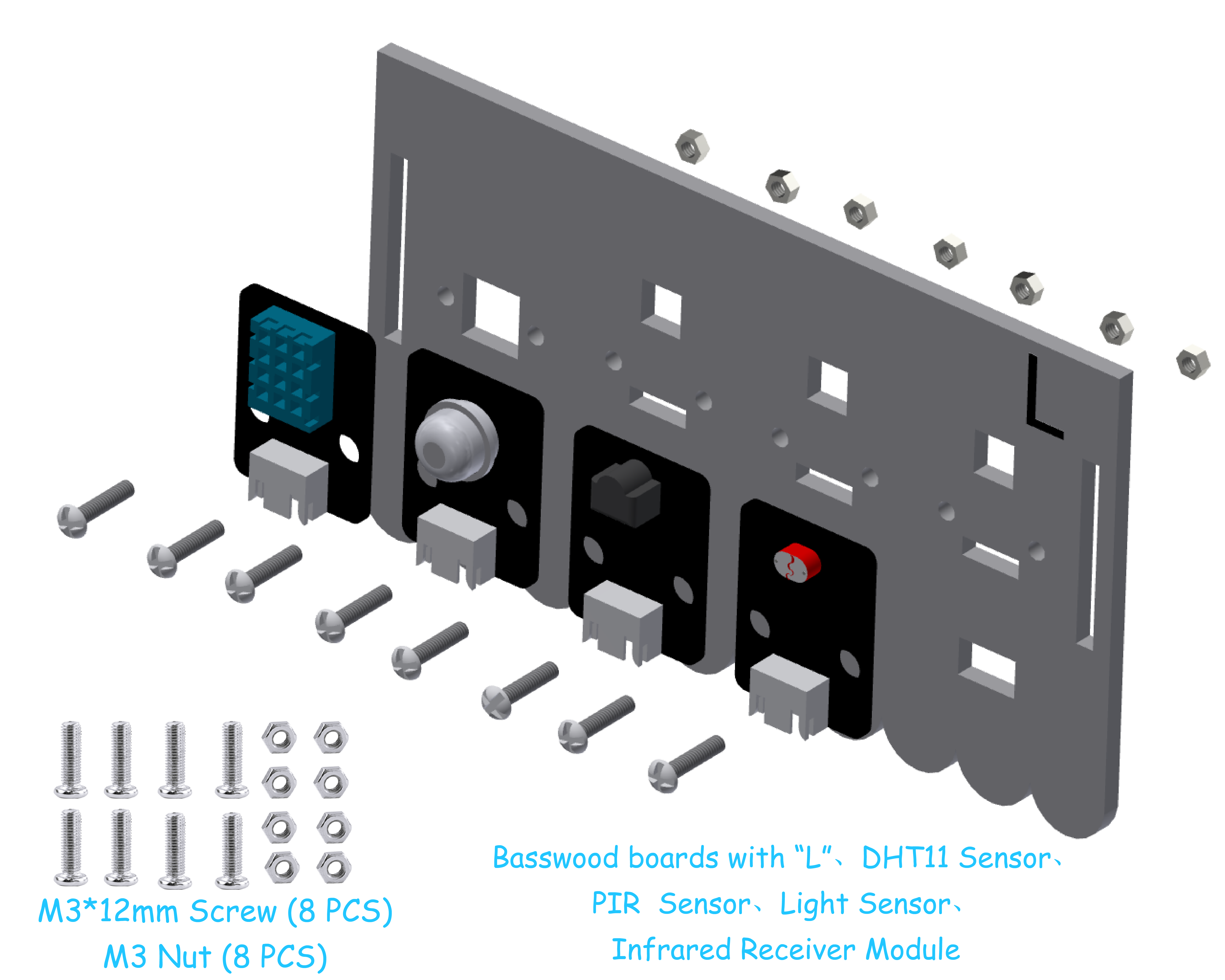
Parts list: Basswood boards with “L”、DHT11 Sensor、PIR Sensor、Light Sensor、Infrared Receiver Module、M3*12mm screw (8 PCS)、M3 Nut(8 PCS).
Precautions
This step requires using a 3-pin cable to connect the following sensor module to the expansion board.
DHT11 Sensor —— IO15、PIR Sensor —— IO33、Light Sensor —— IO34、Infrared Receiver Module —— IO32.
Step 4-2:Install Solar LED
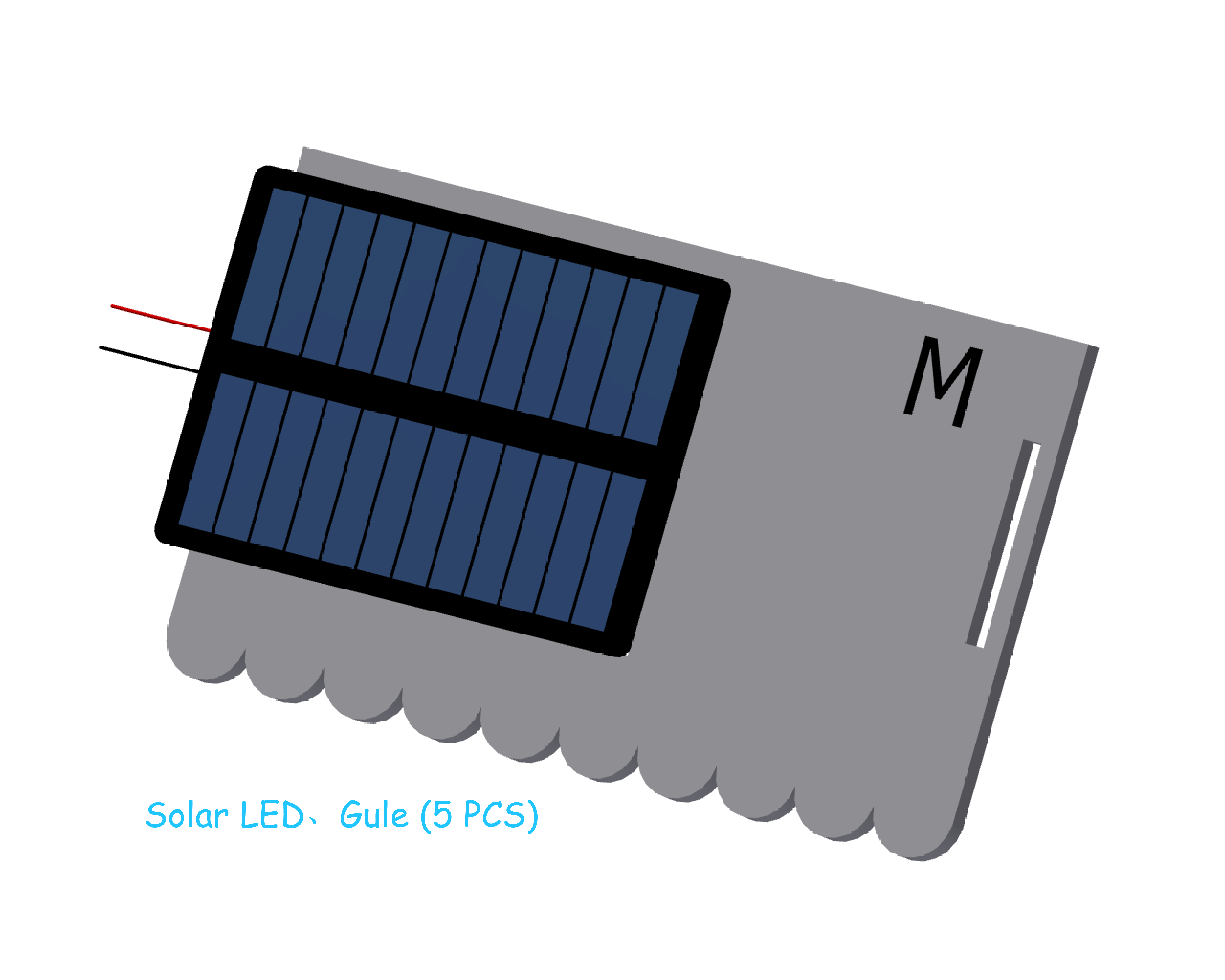
Parts list: Basswood boards with “M”、Solar LED、Glue(5 PCS).
Precautions
In this step, five round adhesive dots are needed to fix the solar panel to the wooden board M.
Step 4-3:Install Roof
Parts list: Basswood boards with “L、M”、 Blue Latch(4 PCS).
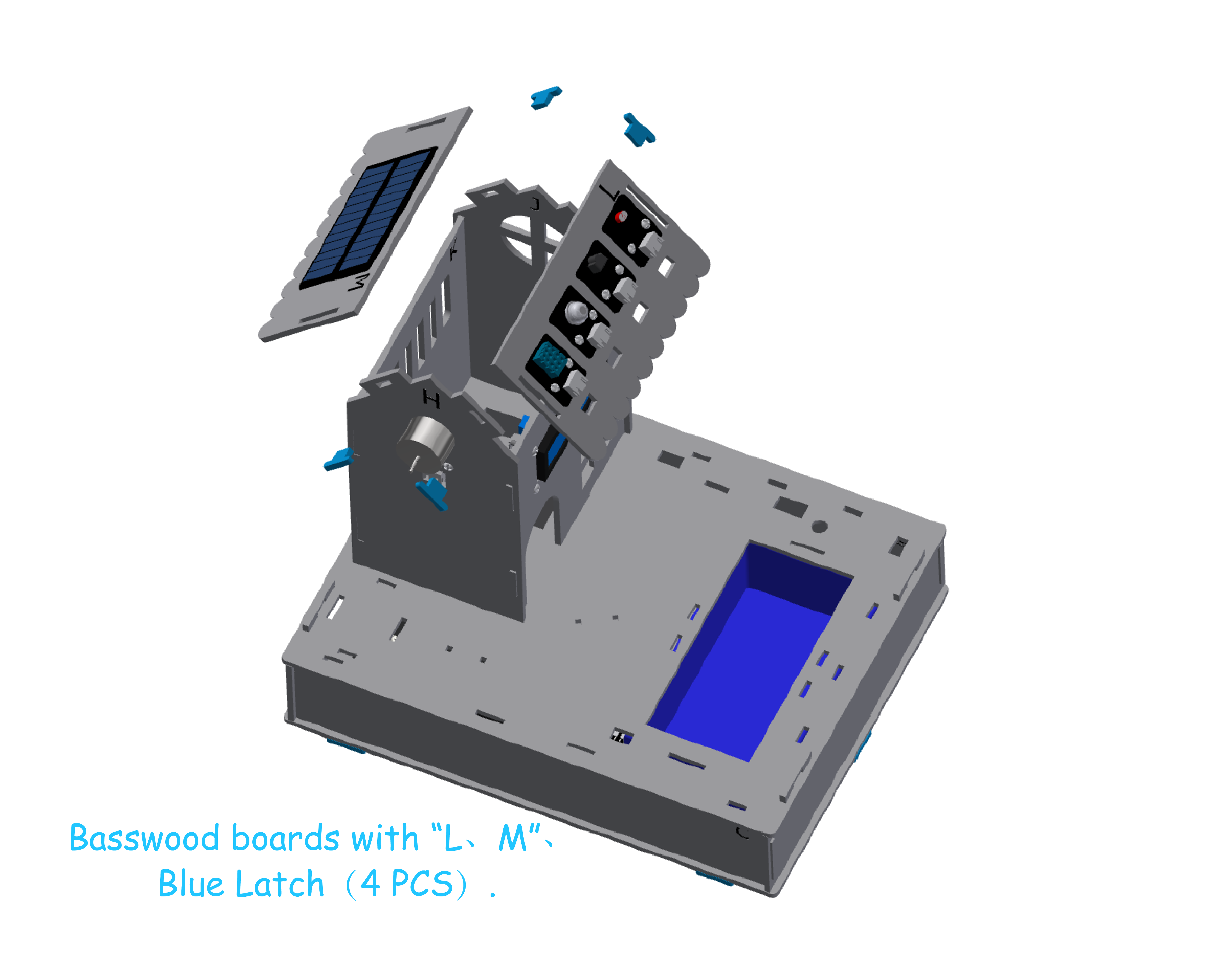
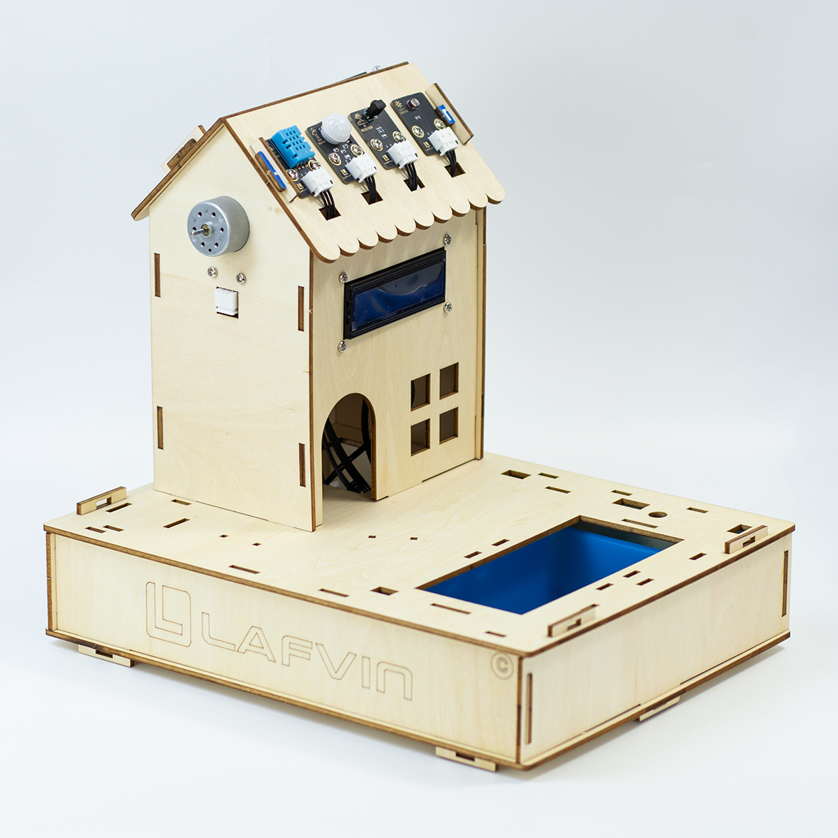
The house is assembled as shown in the picture.
3. Waterwheel Assembly
Step 1:Install Water Pump
Parts list: Basswood boards with “P”、Water Pump、Water Pipe、Glue(1 PCS).
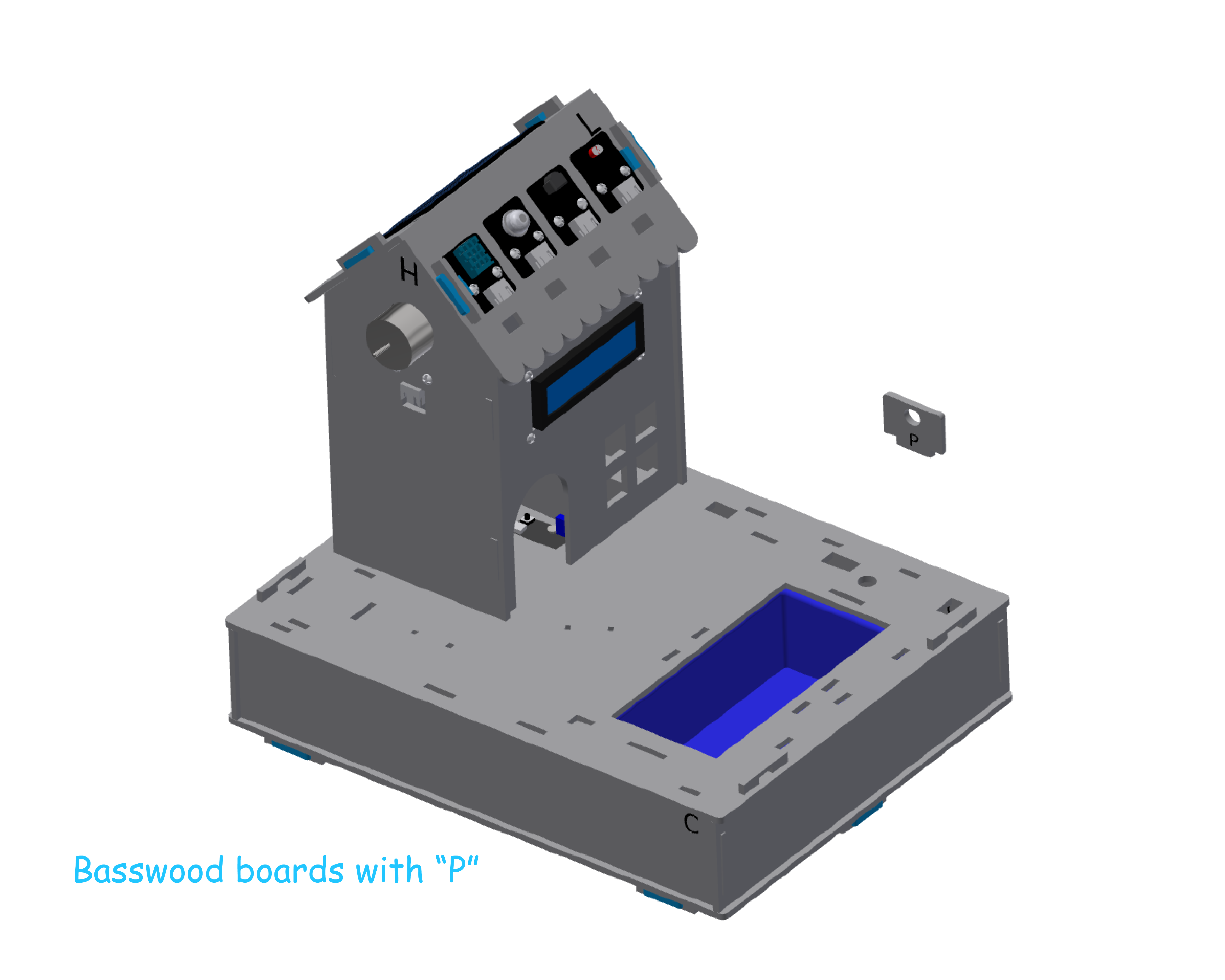
Precautions
In this step, connect the water pump to the XH2.54-2Pin interface of the relay module and short COM to GND using a jumper cap.
When connecting water pipes, maintain their natural curvature and avoid forcibly bending them at the joints to prevent flattening the pipes and causing water flow interruption.
After installation, a water test should be conducted, and the position of the water pipes should be adjusted according to the water flow conditions to ensure that all joints are tightly connected without leaks or overflows.
After adjusting the position of the water pipes, you can use round adhesive dots to fix the water pump inside the water tank.
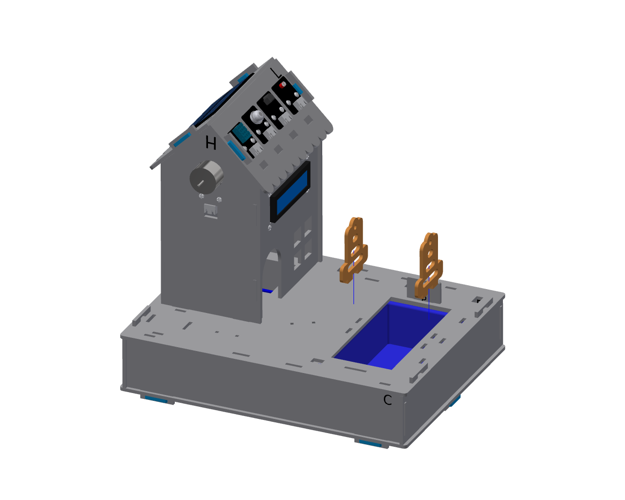
Step 2:Install Waterwheel Support
Parts list: Yellow painted waterwheel support wooden planks(2 PCS).
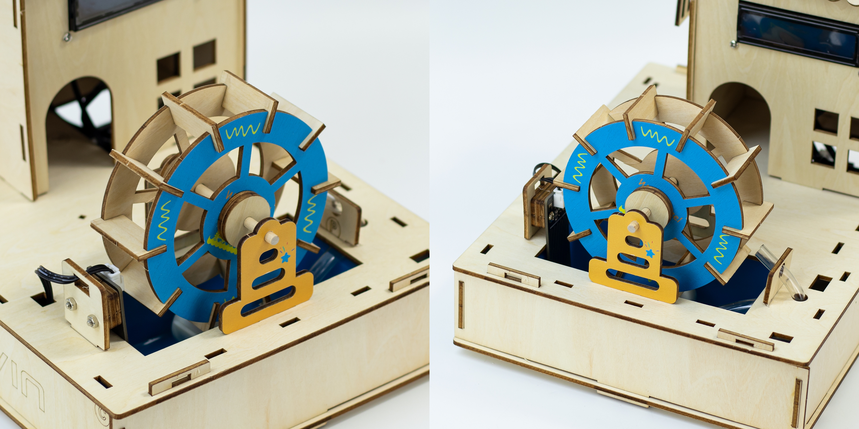
Step 3:Install Water Wheel
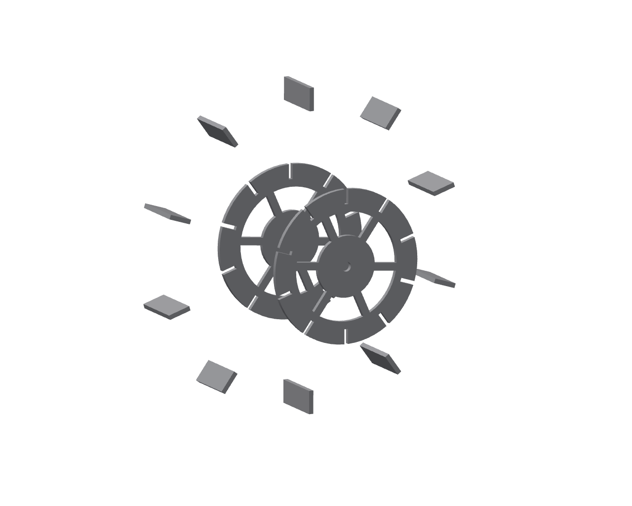
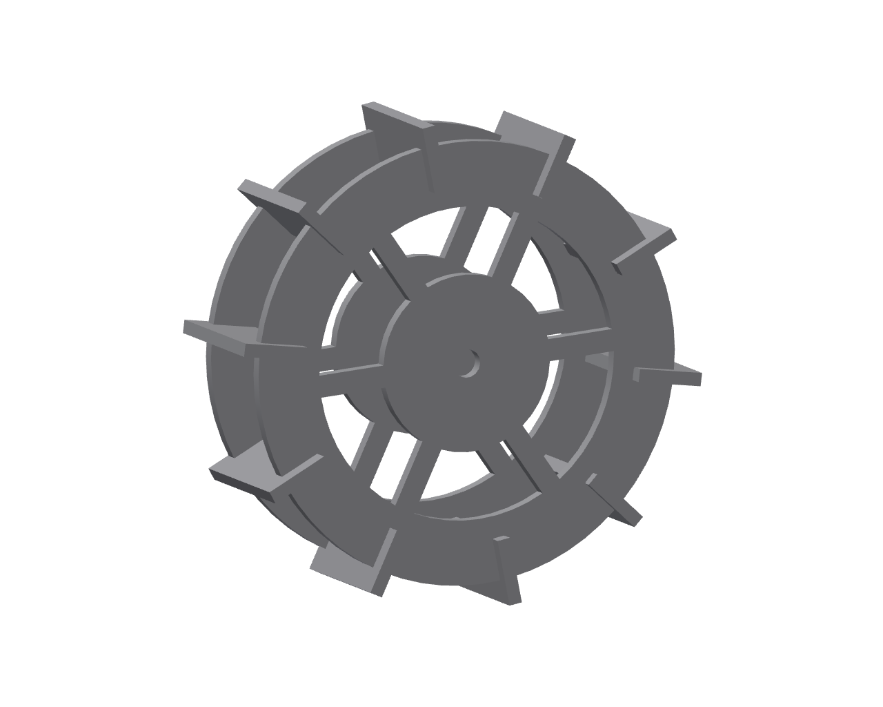
Parts list: Waterwheel(2 PCS)、Waterwheel baffle(10 PCS).
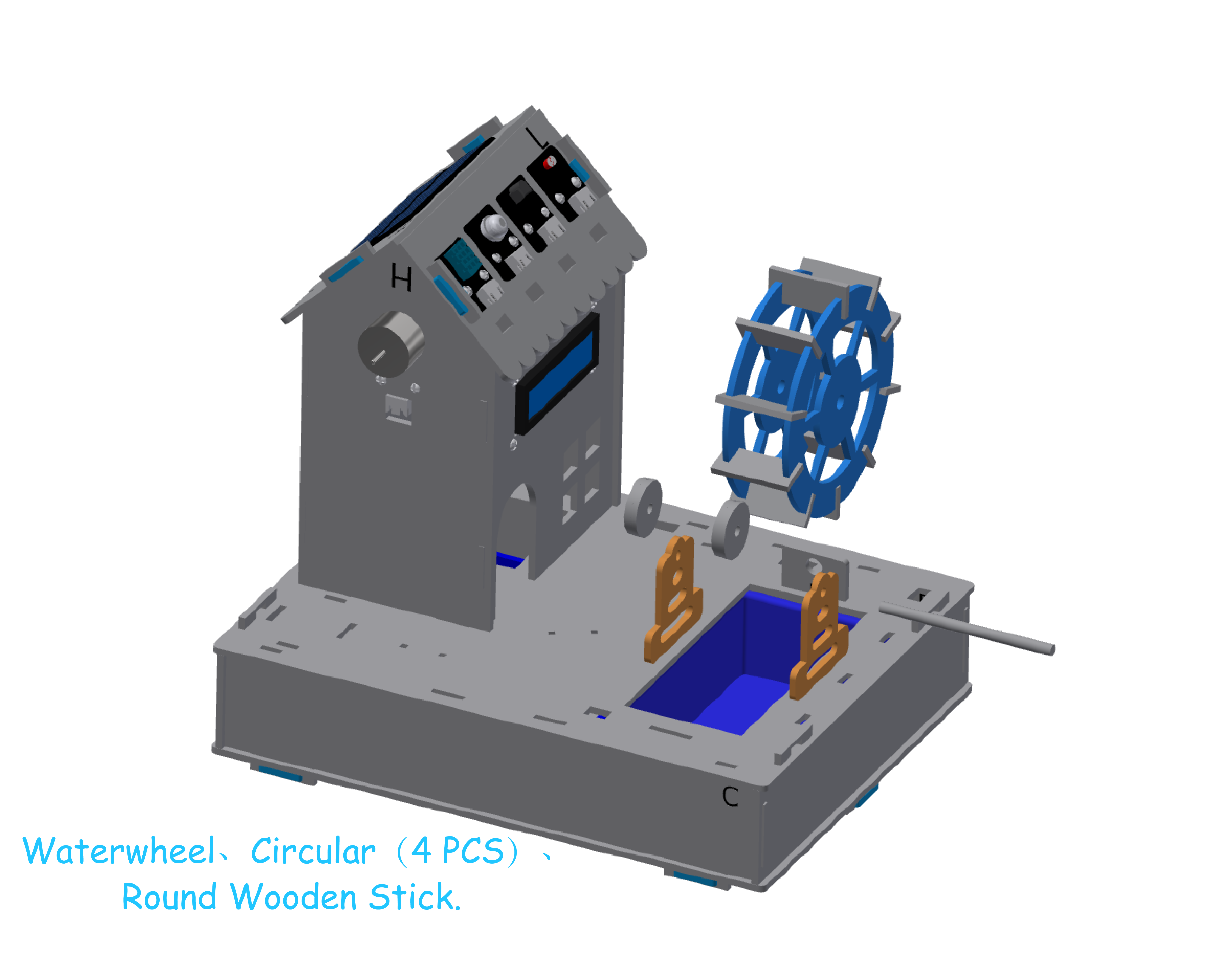
Step 4:Install WaterWheel
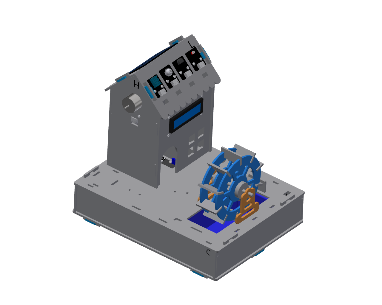
Parts list: Waterwheel、Circular(4 PCS)、Round Wooden Stick.
Precautions
When installing the fixing ring, a gap of about 3mm should be left on both the left and right sides to ensure that the waterwheel can rotate freely.
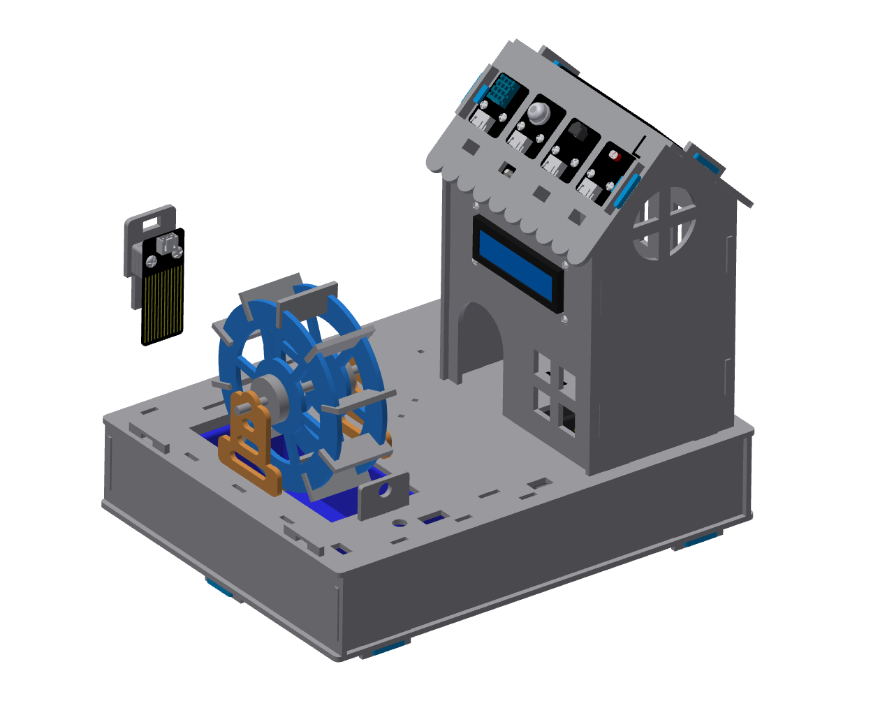
Step 5:Install Water Level Sensor
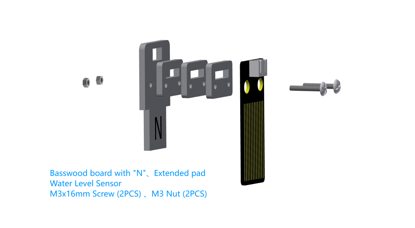
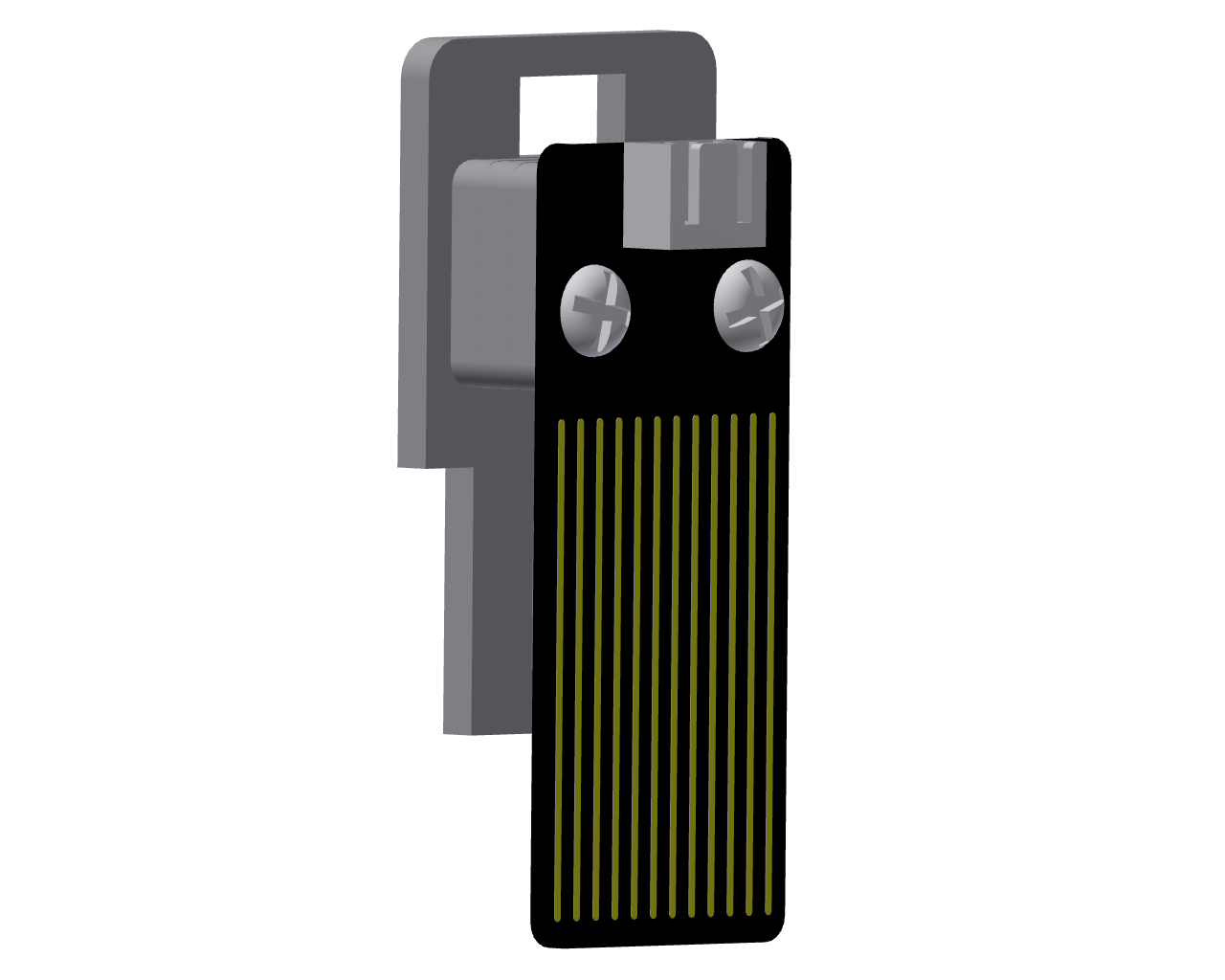
Parts list: Basswood boards with “N”、Extended pad(3 PCS)、Water Level Sensor、M3*16mm screw (2 PCS)、M3 Nut(2 PCS).
Precautions
This step requires using a 3-pin cable to connect the water level sensor to the IO36 pin of the expansion board.
The waterwheel assembly is shown in the picture below.
4. Decorative Assembly
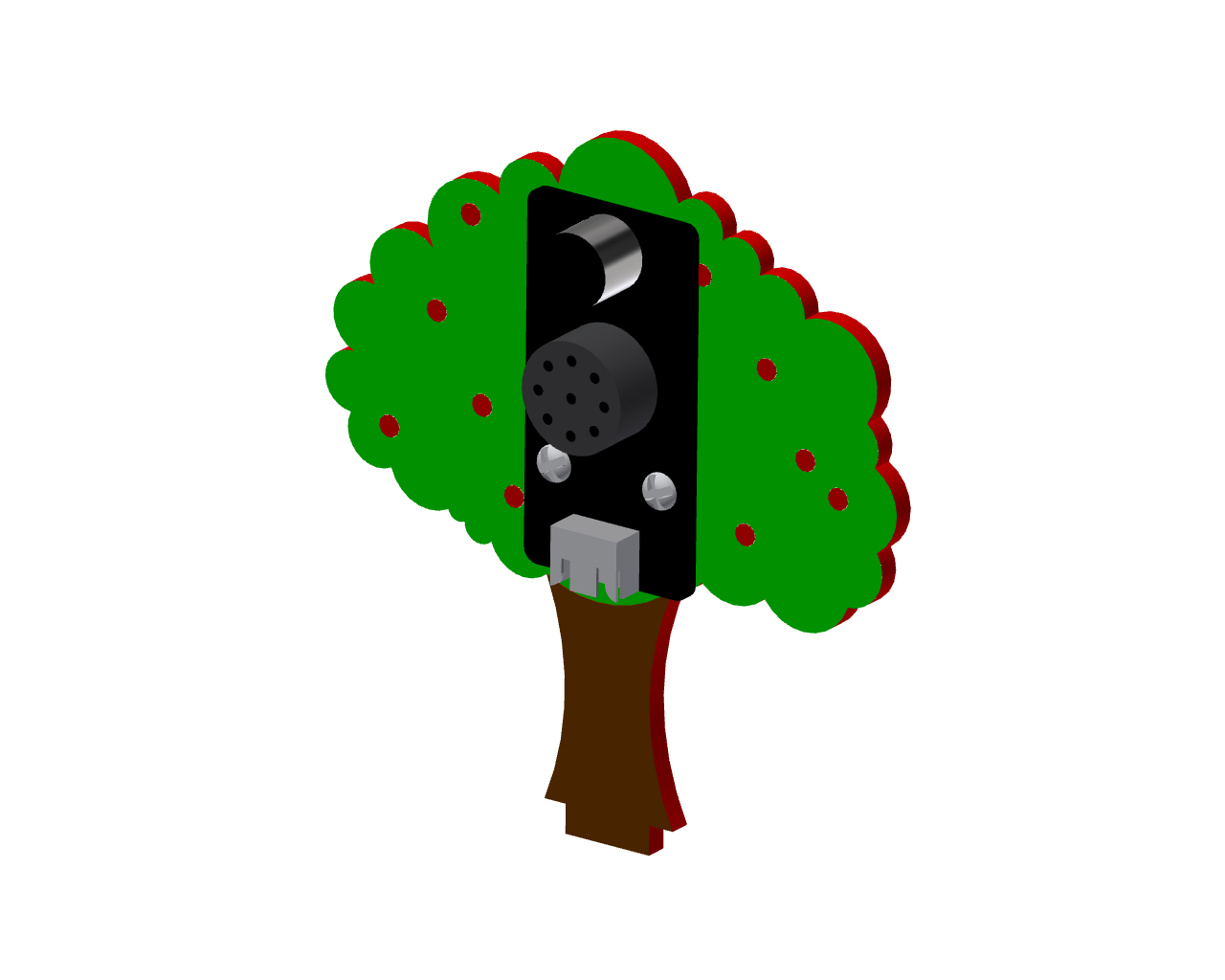
Step 1:Install Speech Recognition Module
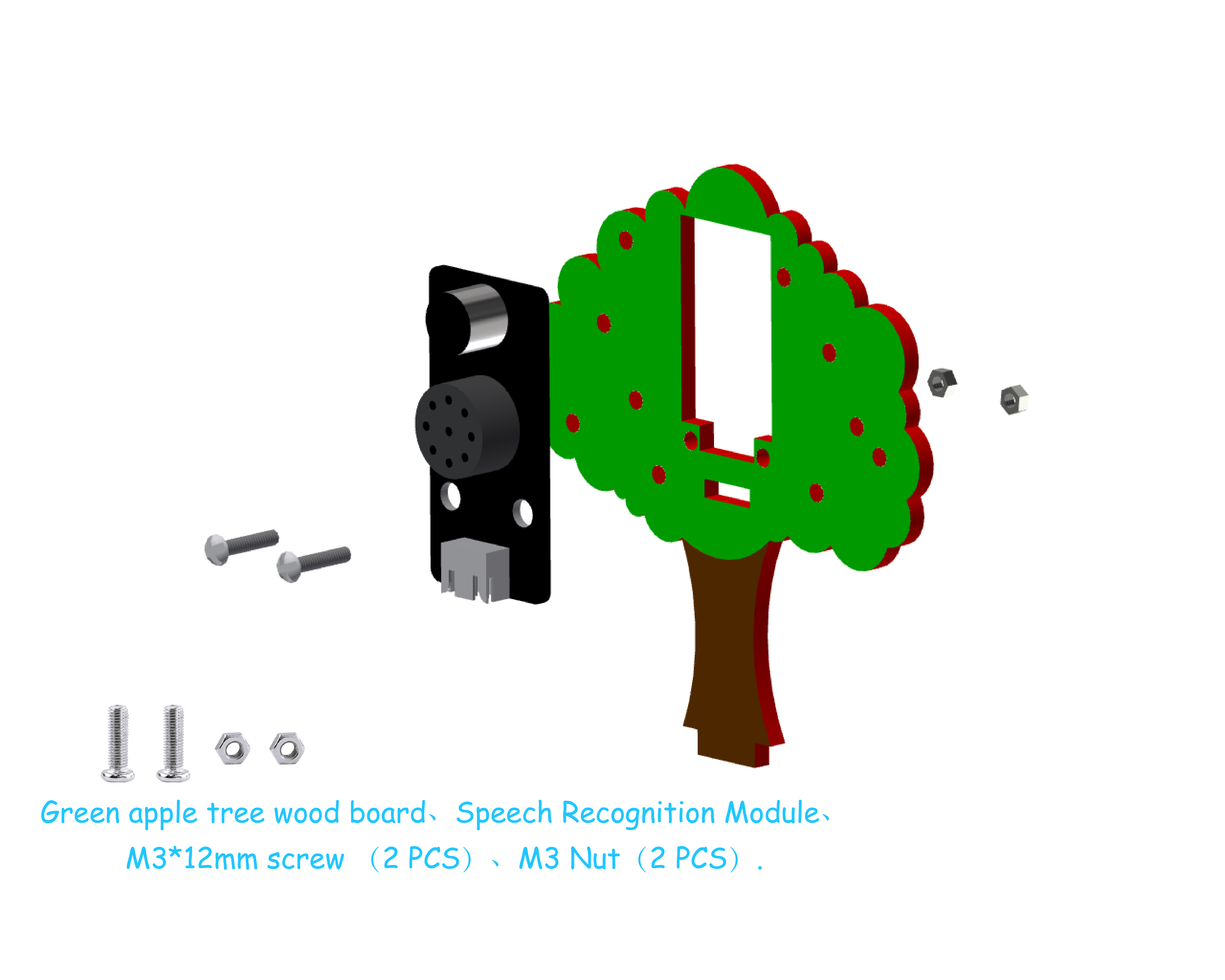
Parts list: Green apple tree wood board、Speech Recognition Module、M3*12mm screw (2 PCS)、M3 Nut(2 PCS).
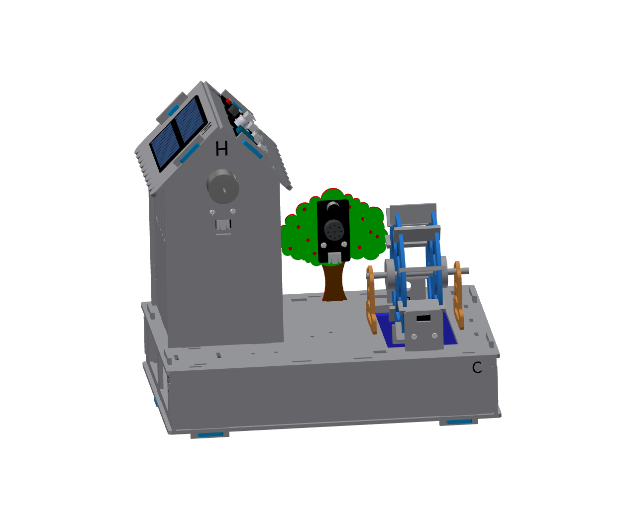
Precautions
This step requires using a 4-pin cable to connect the voice recognition module to the IO16/17 pins of the expansion board.
Step 2:Install Buzzer Module
Parts list: Yellow short-side fence planks、 Buzzer Module、M3*12mm screw (2 PCS)、M3 Nut(2 PCS).
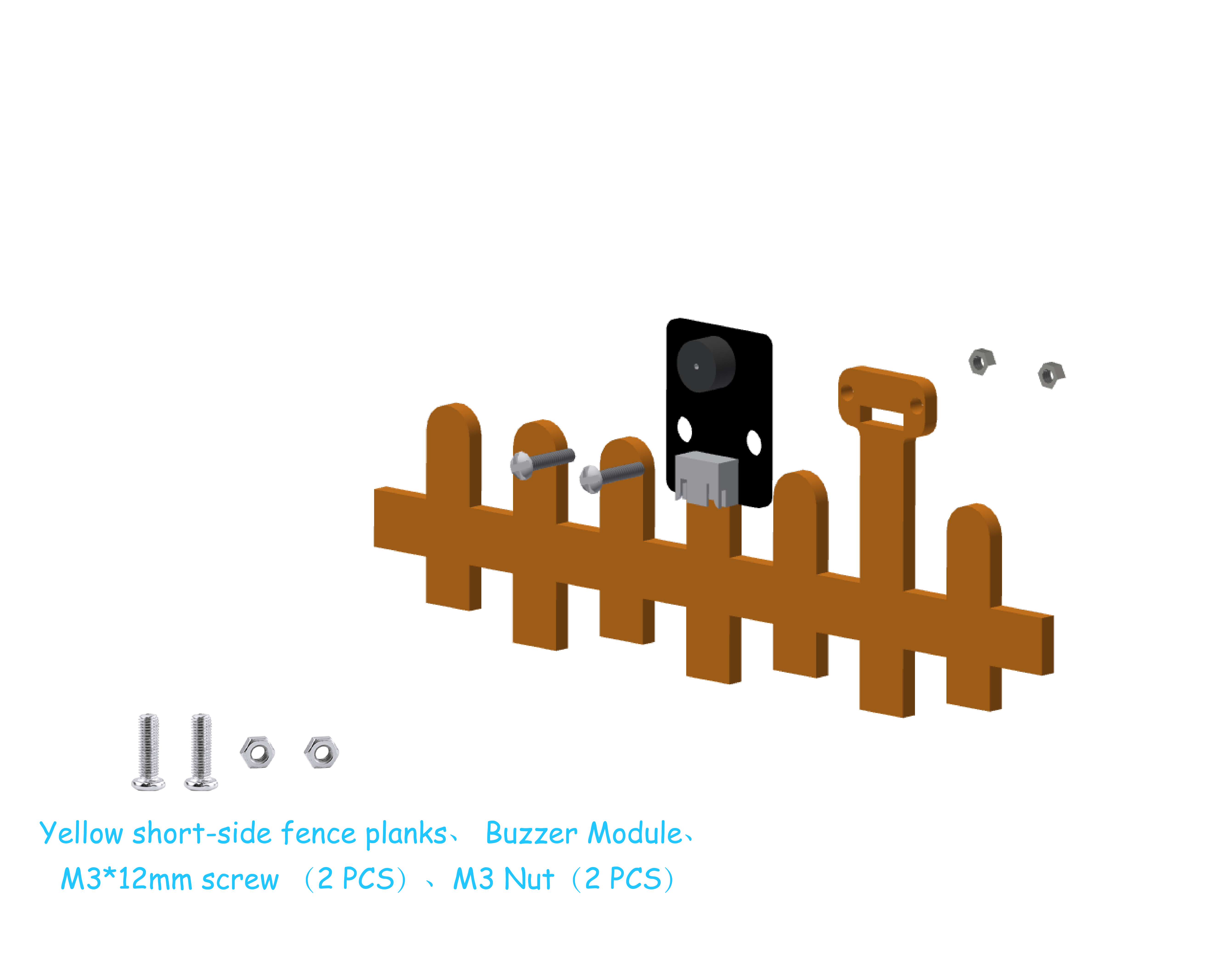
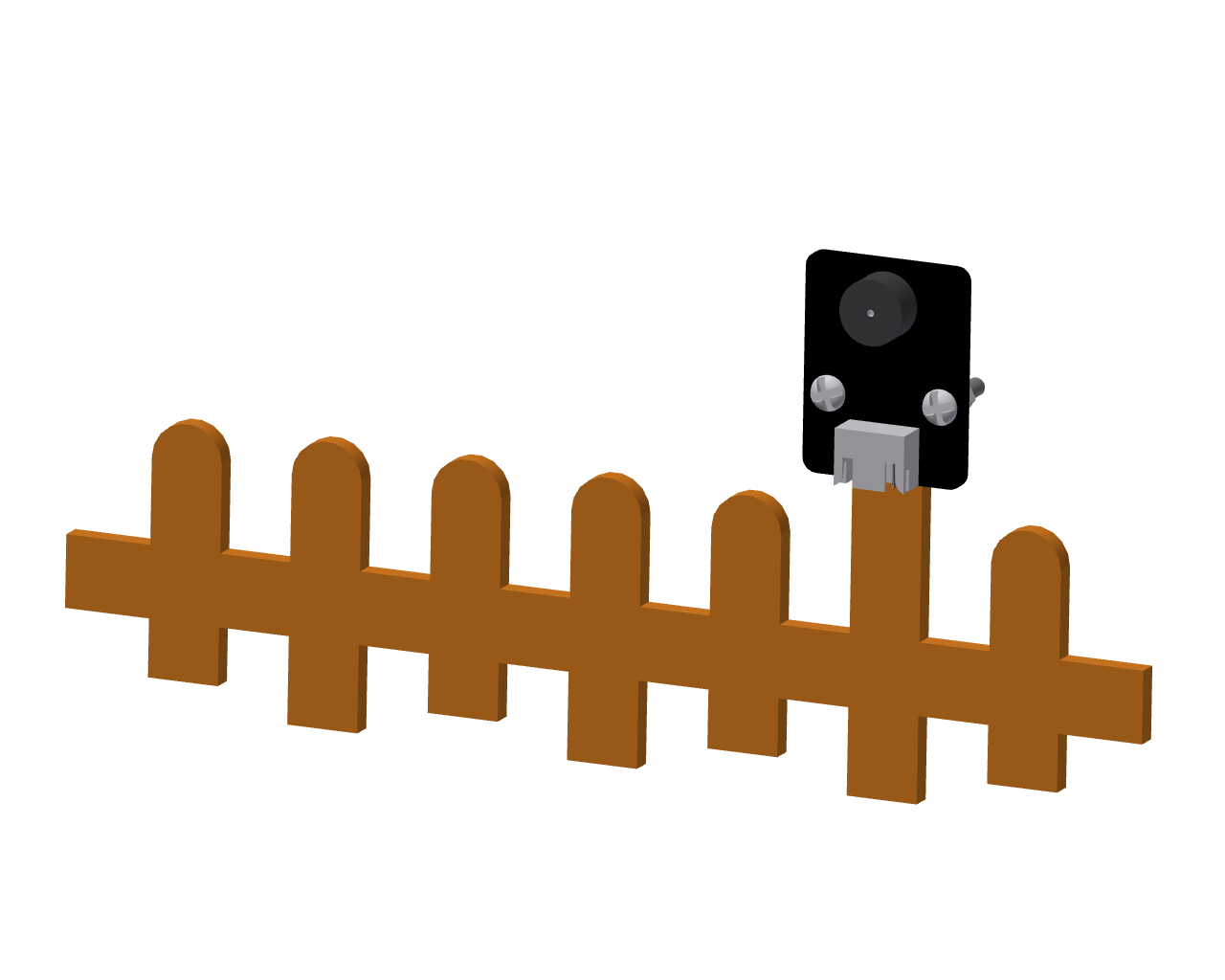
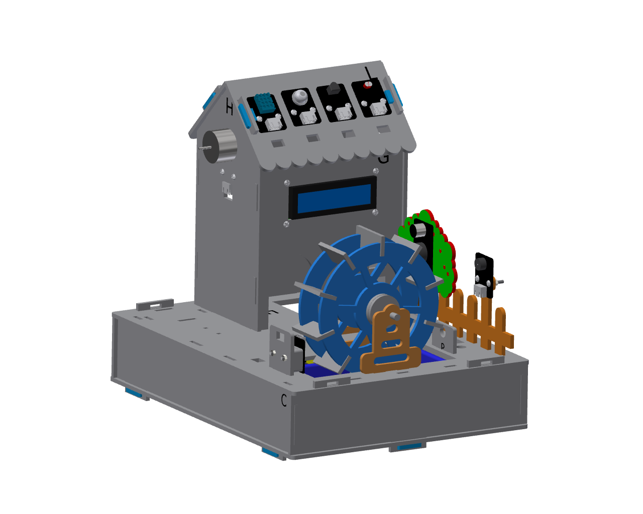
Precautions
This step requires using a 3-pin wire to connect the buzzer module to the IO13 pin of the expansion board.
Step 3:Install RGB LED Strips
Parts list: Yellow long-side fence planks、RGB LED strips.
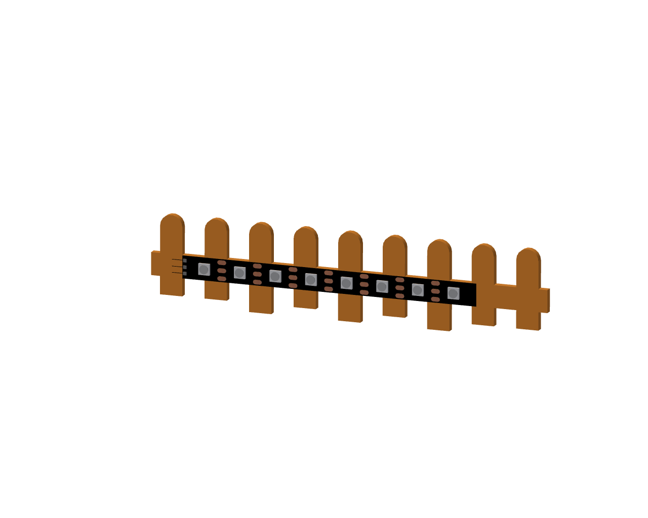
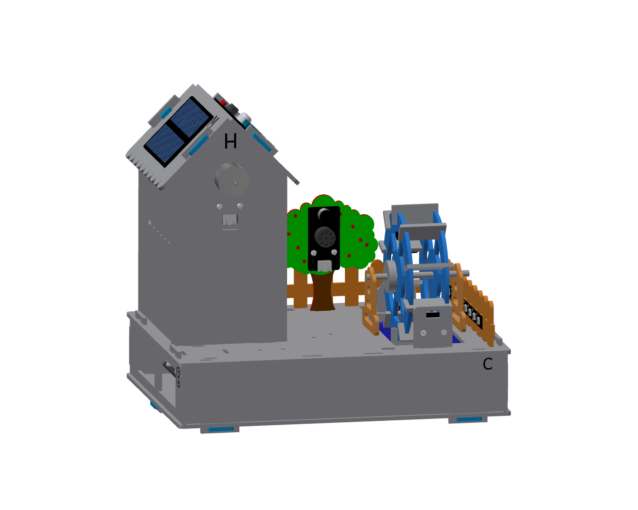
Precautions
First tear off the blue tape on the back of the light strip, and then stick the light strip on the back of the fence.
This step requires using a 3-pin wire to connect the RGB LED strip to the IO12 pin of the expansion board.
Step 4:Install Feeding Trough
Parts list: Semi-circular feeding trough wooden board (2 PCS)、rectangular feeding trough wooden board(2 PCS).
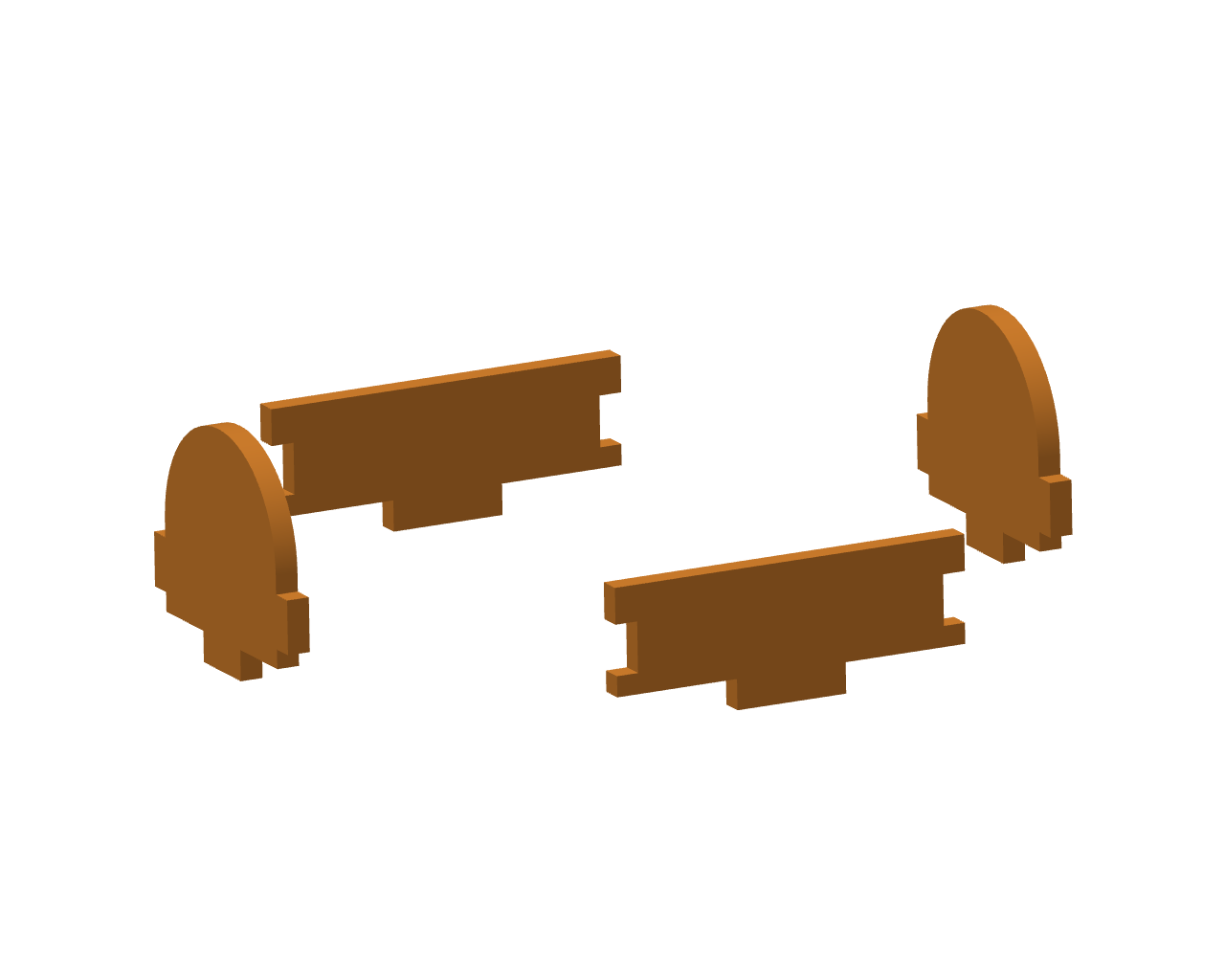
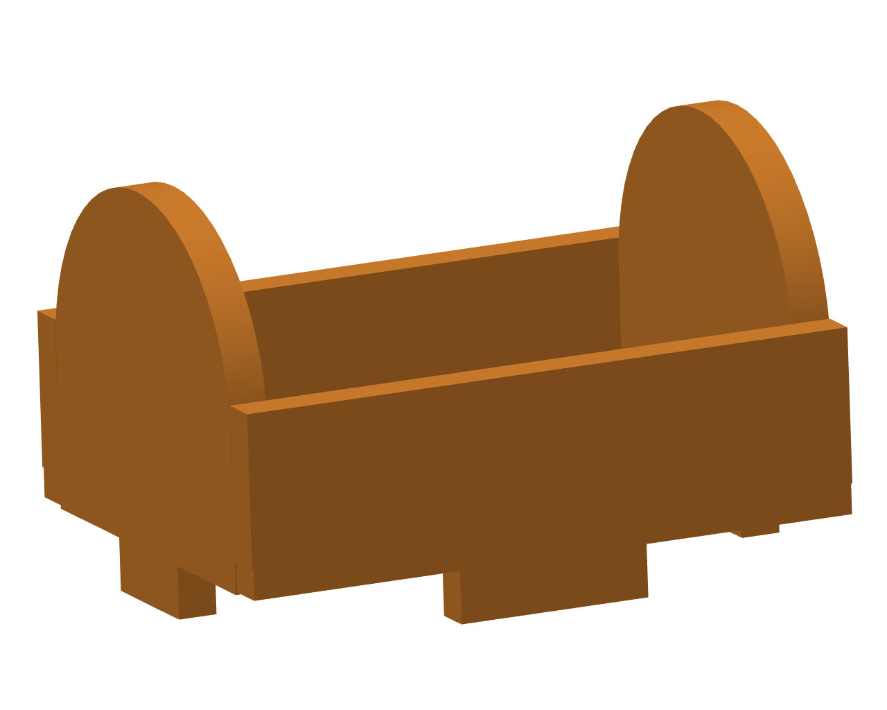
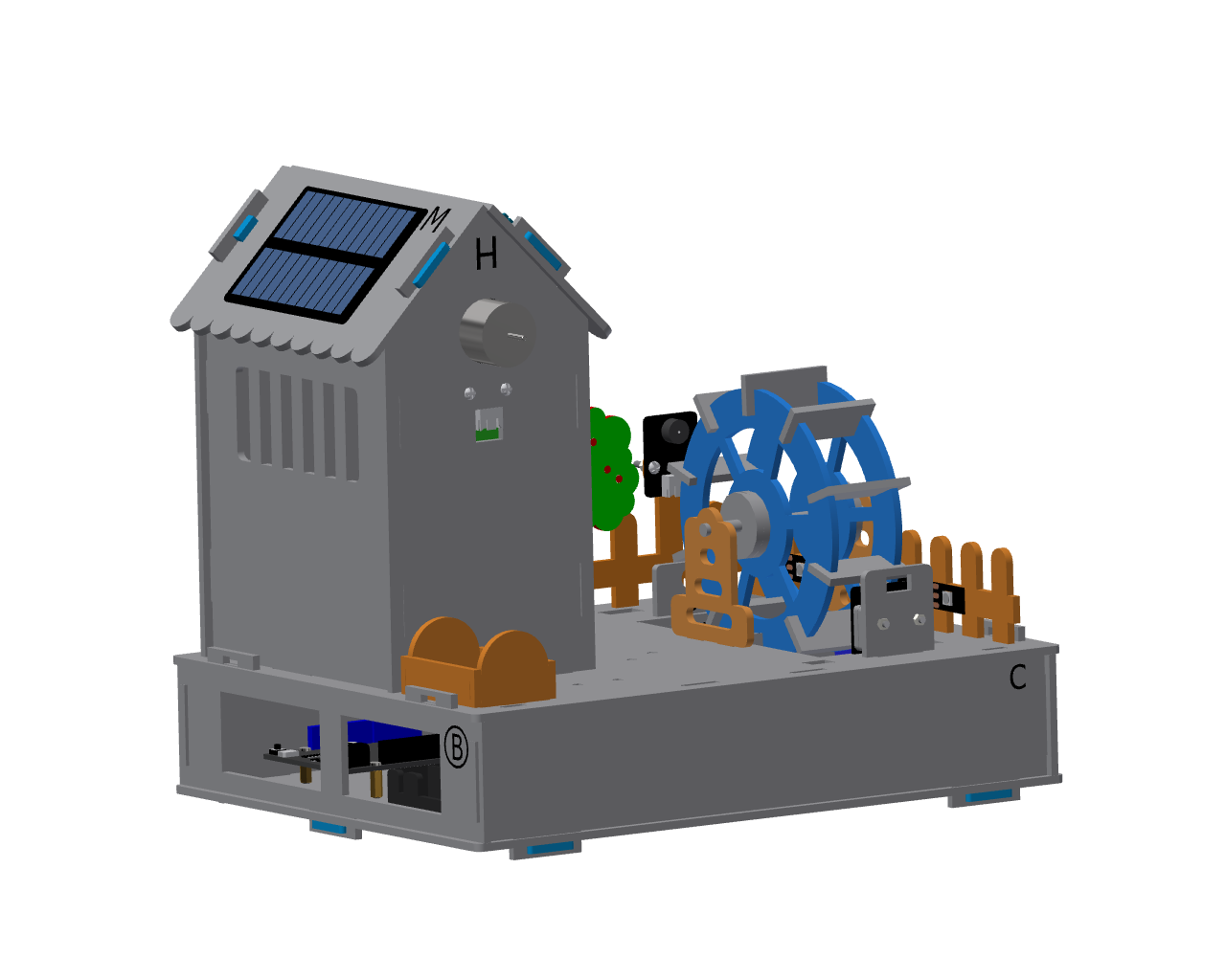
Step 5:Install the sheep
Parts list: Sheep plank.
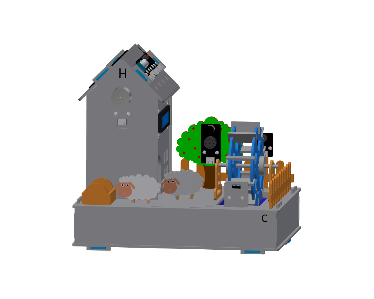
Step 6:Install Fence Gate
Parts list: Bull-head shaped fence gate planks
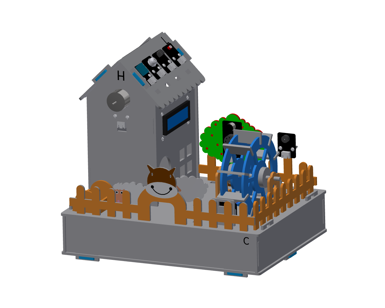
Step 7:Install Windmill Blades
Parts list: Green windmill blade wooden board
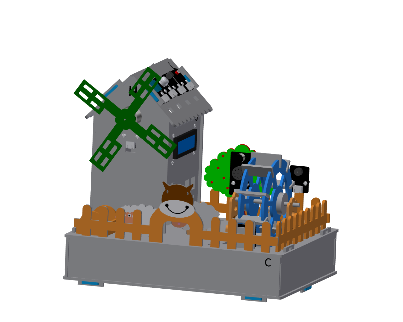
Step 8:Install Latch
Parts list: Blue Latch(4 PCS)
Precautions
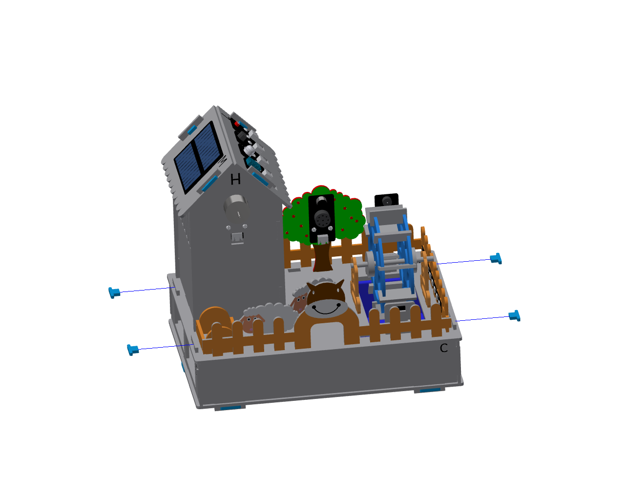
After ensuring the module’s wiring is connected and the power-on test shows no problems, install the latches and tighten them.